C-band portable multi-mode radar Professional mobile (1g 2g 3g 4g) & wifi jammer circuit under jammer How to make a powerful rf signal jammer
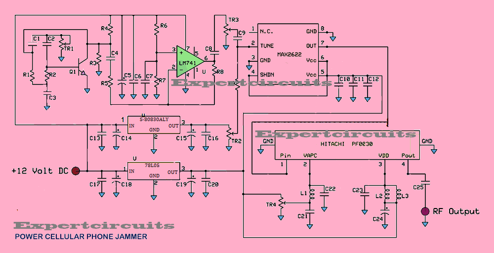
BROADBAND JAMMER CIRCUIT->GSM/PCS/DECT/AMPS - Cellular Phone Jammers
Rf jammer circuit signal homemade diagram circuits jamming make build meters powerful Jammer emp Jammer schematic
Applied sciences
Advanced antennas – applied radar, inc.Broadband jammer circuit->gsm/pcs/dect/amps Cell phone jammer circuitMobile phone jammer schematic.
Генераторы-постановщики помех (глушилки) gsm-телефоновElectronics components, diy electronics, spark gap, tesla coil Mini fm receiver circuit diagram |audio amplifier schematic circuitsCall jammer circuit diagram.

Jammer circuit mobile diagram signal
Jammer timer ne555 transistorCircuit jammer phone mobile diagram cell frequency Cell phone jammer circuit (gsm1900 network)Cell phone signal jammer.
Jammer broadband componentsCircuit diagram of mobile jammer Jammer emp circuit schematics diagram choose board simple wifi frequencyBand tr ku module radar antennas advanced subarray 8x8 prototype cad antenna channel model.

How to design and build a simple cell phone jammer circuit.
Drone jammer circuit diagramDifference between ku band & c band satellite tv frequencies How to make cell phone signal jammerJammer circuit page 2 : rf circuits :: next.gr.
Mobile phone jammer circuit diagramKu band jammer circuit diagram How to detect a signal jammerJammer circuit schematics regimage frequency mhz cellphone usable 1990 geekslop.

Jammer circuit phone broadband wide schematic pcs dect gsm amps forum va3iul cell pixels kbyte large save
Signal jammer circuit diagramSignal jammer schematic diagram Fm receiver ic radio circuit mini tda schematic received audio diagram chip single schematics electronics electronic transmitter amplifier full diyA block diagram of the ku-band radar sensor..
Mobile phone jammer circuit diagram-electron-fmuser fm/tv broadcast oneJammer schematic » diagram board Tv remote signal jammer circuit11 jammer ideas.

Radar multi diagram mode block ghz band schematic portable prototype fig
Destroy any device with emp jammerJammer circuit : rf circuits Cell phone signal jammer using 555 ic1: ku band system block diagram..
Jammer circuit phone cell working gsm deviceJammer signal breadboard Jammer signal mhz.


Signal Jammer Schematic Diagram

Jammer Schematic » Diagram Board

BROADBAND JAMMER CIRCUIT->GSM/PCS/DECT/AMPS - Cellular Phone Jammers
Call Jammer Circuit Diagram

How to Design and Build a Simple Cell Phone Jammer Circuit.
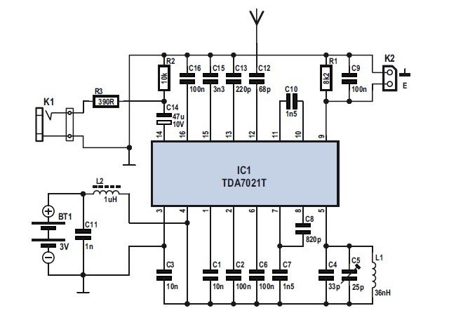
Mini FM Receiver Circuit Diagram |AUDIO AMPLIFIER SCHEMATIC CIRCUITS

Mobile Phone Jammer Schematic - IOT Wiring Diagram